
Materials Science Models
The operational life of complex rotating equipment does not always match design life requirements identified during physical test. In fact, Sentient Science calculated ~68% difference from design qualification to real-world application.
The contributing factors for this difference are material quality, surface roughness, microhardness and manufacturing processes that impact the operational life of components. Material microstructure and surface features are exceedingly sensitive to crack initiation, which lead into propagation and finally spall generation. Once spall generation occurs, component replacement is imminent. Microstructure characteristics include non-metallic inclusions (shape, grain size, type and orientation), morphology and volume fraction of different phases. Collectively these have direct influence on rolling contact fatigue.
Sentient Science’s materials science computational testing process can be used to investigate inclusions post metallographic process. The result is a meaningful root cause analysis (RCA) of field failures. This process builds the component catalogue for Sentient’s bearing(s) and gear(s) library. DigitalClone Live applies Sentient’s material library for full system digital modeling to create the materials life models. The process integrates the live operational data from the field to update the component life predictions – turning results into life extension actions.
Sentient Science employs 18+ Ph.Ds. with detailed expertise in materials science, data science and mechanical engineering from the world’s top universities that analyze, research and assess the science behind why materials fail in operation. The facility in West Lafayette, IN is home to Sentient’s bearing and gear team, specializing in detailed failure modes for analysis of critical components in the drivetrain of fielded wind turbines.
Use Case
In one example, multiple wind turbine gearboxes had intermediate pinion failures during a similar timeframe. The gearboxes were refurbished by an aftermarket supplier other than the original equipment manufacturer (OEM). The replacement gearboxes had been in service less than 3 years and the intermediate pinions failed catastrophically – multiple tooth fractures, with liberated teeth that led to consequential damage on other components.
Sentient Science conducted a metallurgical analysis on the cross-sections of the shaft taken from locations within the fractured teeth. Fractographic examinations found that the cracks originated at subsurface material defects identified as oxide inclusions containing aluminum and silicon. During normal cyclic loading, the inclusions acted as localized stress, causing premature cracks in the gear. Inclusions are common in all steels; however, ISO standards specify the steel cleanliness grade according to size and quantity of allowed inclusions. In the wind turbine gearbox application, the standard recommended a minimum grade of MQ, which is comparable to AGMA Grade 2. The failed pinion did not meet the MQ cleanliness required, because the supplier had a poor material batch issue, which caused the field failures.
The site owner identified the field turbines that had pinions manufactured with the same batch of steel. Through up-tower inspections, the in-situ shaft of the at-risk turbines were replaced. To mitigate future risk of failures a gearbox repair specification requirement was implemented to meet material cleanliness of MQ-grade through a new gear manufacturing quality control process using non-destructive testing. Alternative recommendation suggested a design change to the steel type and composition of the alloying elements. A material with improved core toughness and harden ability characteristics would likely reduce the risk of crack propagation in the presence of inclusions.
Computational Test & Analysis
The scientists at the laboratory offer full-service scientific analysis of the performance metrics of bearings and gears under observation.
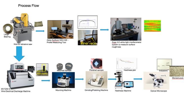
The following process is used:
Step 1 – A wet-cut abrasive saw is used to cut a sample from the outer race and inner race for bearing analysis
Step 2 – High precision contour measuring station from the Surfcom NEX 0490 is used to measure tiny radii, bevels, angles, cut ins and length tolerances
Step 3 – Uses the Zygo 3-D white light inferometer system to measure the surface roughness of the materials
Step 4 – The Wire Electrical Discharge Machine (EDM) cuts bearing sections for metallographic analysis. EDM cuts high-strength steels without damage to material microstructure
Step 5 – Uses a 3D mounting machine to scan the geometry measurements of the sample, plus the housings, shaft and gears to re-engineer the gearbox for CAD modeling. The scans are used to build the digital system model (step 1) of the Six Step Process
Step 6 – The coordinate measuring machine looks for the geometry measurements
Step 7 – The grinding/polishing machine polishes the sample
Step 8 – Uses a hardness machine to measure material hardness
Step 9 – Analyzes inclusions in the microstructure using an optical microscope
Why perform mechanical measurement, surface, and metallographic analysis?
Compare component and/or manufacture variability
Understand key inputs to component life
Identify manufacturing quality and design shortfalls
Identify root cause of failure
Why perform oil & grease performance analysis?
Compare oil and grease attributes under various loads
Select Oil and Grease based on performance
Life extension actions based on corporate business rules
What do you receive in Final Report?
Lubricant test report (if applicable)
Details of mechanical measurements
Surface roughness analysis
Material quality summary
DigitalClone Enables:
30% Reduction in Parts Costs
50% Reduction in Labor Costs
50% Reduction in Fleet Failure Rates
6% to 1% Reduction in Failure Rates of New Product Design
$10:$1 Definable Savings